- Thread Types
1.1 The development history of threads
Threads are widely used in the field of mechanical manufacturing due to their ease of assembly, disassembly, and removability. Thread standards have become one of the important foundational standards in machinery. After the first industrial revolution, the British invented the lathe, dies, and taps, laying the technical foundation for the mass production of threaded components. In 1841, Joseph Whitworth of Britain proposed the world’s first national thread standard (BS 84, Whitworth thread, B.S.W, and B.S.F), establishing the technical system for thread standards. In 1905, William Taylor of Britain invented the design principle for thread gauges (Taylor’s principle). From then on, Britain became the first country in the world to fully master thread processing and inspection technologies. The British imperial thread standard is the ancestor of the current thread standards worldwide and was the first to gain global recognition. The American National Thread (N) standard was developed based on the British Whitworth thread. After World War I, it evolved into the Unified Thread (UN) used by the Allied forces in World War II. This was the first international standard to be recognized by an international organization. The American pipe thread standard was independently developed by Americans and, together with the British imperial pipe thread, forms the two pillars of the world’s pipe thread standards today. The American Acme and buttress threads were also recognized among the Allied nations during World War II. Therefore, the American thread standards have an extremely significant impact on modern international trade. The metric ordinary thread (M) originated from the American National Thread (N) and has been widely used in continental Europe, being incorporated into ISO standards. When the metric system (where the meter is the unit of length) was established as the international legal unit of measurement, it further elevated the status of metric ordinary threads in international trade.
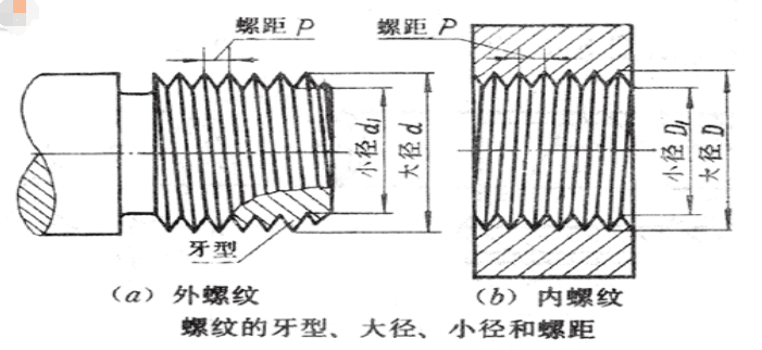
1.2 Metric thread
Metric thread, a type of thread standard, is also known as the metric screw thread. (GB/T 192-2003)
1.Metric ordinary threads are denoted by the uppercase letter M. Metric threads feature a 60-degree equilateral thread profile and are specified by their pitch, using metric units (such as mm).
2.Metric ordinary threads are divided into two types based on pitch: coarse threads and fine threads.
2.1. Coarse threads typically do not specify the pitch in their designation. For example, M20 denotes a coarse thread. Fine threads, however, must indicate the pitch in their designation. For instance, M30x1.5 represents a fine thread with a nominal diameter of 30 mm and a pitch of p=1.5 mm.
2.2. Ordinary threads are used for connecting and fastening mechanical components. Coarse threads are generally more common for threaded connections, while fine threads, compared to coarse threads of the same nominal diameter, offer slightly higher strength and better self-locking performance.
1.3 Introduction to imperial threads
British Standard Threads feature an isosceles 55-degree thread profile. These threads are specified by the number of threads per inch, using imperial units (such as inches). For example, 1/2-14 indicates a thread size of 1/2 inch with 14 threads per inch.
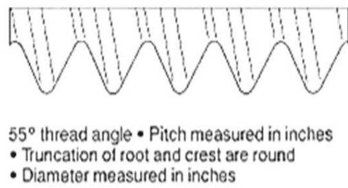
BSPP (British Standard Parallel Pipe) is a 55-degree non-threaded sealing pipe thread, belonging to the Whitworth thread family. The internal taper thread is designated as RP. The national standard symbol is G, representing cylindrical threads. The national standard can be referenced in GB/T 7307-2001, and its corresponding ISO standard is ISO 228/1.
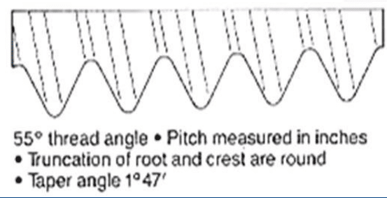
PT (BSPT, British Standard Pipe Taper) stands for Pipe Thread, which is a 55-degree sealing taper pipe thread with a taper of 1:16 and a thread angle of 1° 47′. It also belongs to the Whitworth thread family and is widely used in Europe and Commonwealth countries, particularly in the water and gas pipe industries. The national standard can be referenced in GB/T 7306-2000. Previously, it was referred to as ZG in China. Now, it aligns with the ISO standard (ISO 7/1) and is designated as R (RT). The internal taper thread is Rc, and the external taper thread is R (formerly labeled as PT).
1.4 Introduction to American Standard Threads
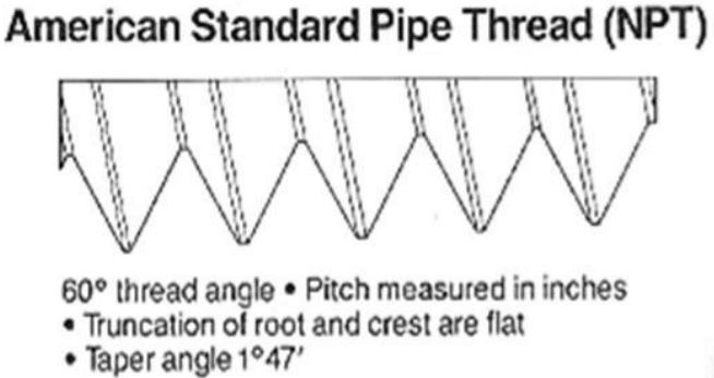
American threads are divided into two categories: the American Standard Pipe Thread (ANSIB1.20) and the Unified Thread Standard (UN series) (ANSIB1.1). American threads feature an isosceles 60-degree thread profile and are specified by the number of threads per inch, using imperial units (such as inches).
NPT stands for National (American) Pipe Thread, which is a 60-degree taper pipe thread standard in the United States, with a thread angle of 1° 47′. It is widely used in North America. The national standard can be referenced in GB/T 12716.
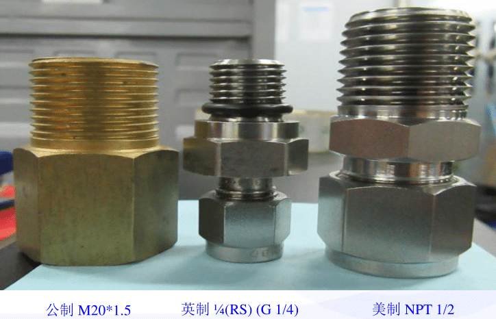
1.5 Main differences among metric, imperial and American threads
A) Metric threads are specified by their pitch, while American and British threads are specified by the number of threads per inch.
B) Metric threads have a 60-degree equilateral thread profile, British threads have an isosceles 55-degree thread profile, and American threads have an isosceles 60-degree thread profile.
C) Metric threads use metric units (such as mm), while American and British threads use imperial units (such as inches).
2. Introduction To Instrument Joints
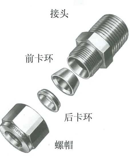
2.1 Structure of instrument joints
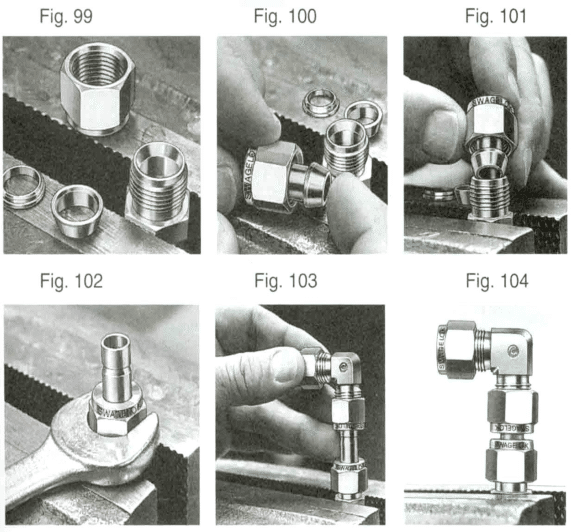
A standard instrument joint (OD joint) consists of a nut, a ferrule (some have only one ferrule), a fitting, and a pipe.
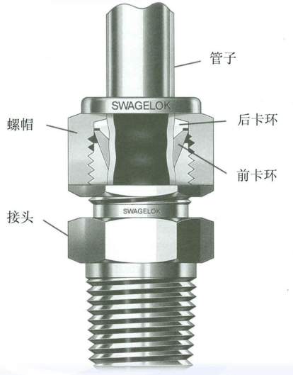
The shape of a standard pipe joint after installation is shown in the figure on the right.
2.2 Installation of instrument joints
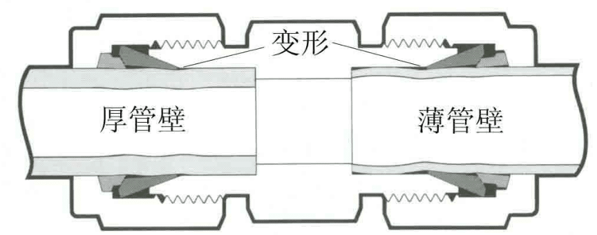
Sealing principle: The ferrule is made to compress the pipe and cause it to deform through tightening the nut, thus forming a seal.
Step 1 :Insert the pipe into the fitting and make sure it reaches the bottom end of the nut.
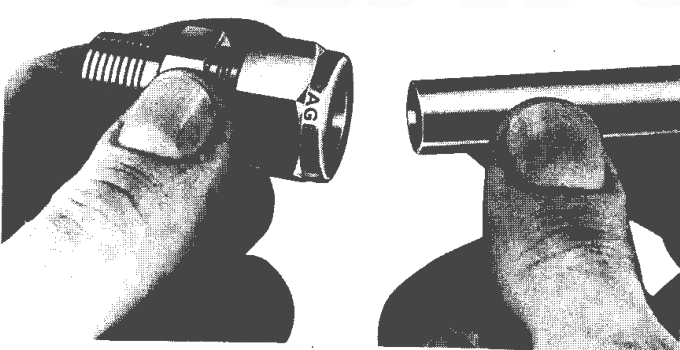
Step 2 :Tighten the nut by hand and make a mark at a certain position (see the mark at the 6 – o’clock position).
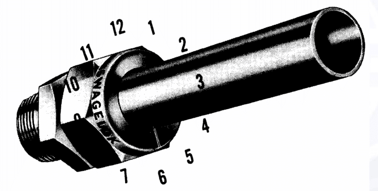
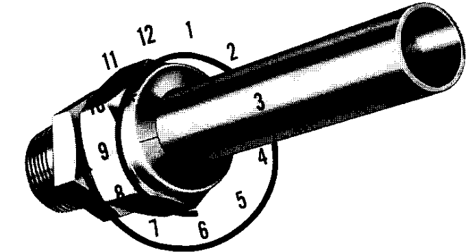
Step 3 :Use a wrench to turn the nut clockwise by 1 and 1/4 turns until the mark reaches the 9 – o’clock position.
Precautions :
- For pipes with a diameter of 1 inch (25 mm) or less, after tightening the nut by hand, turn it an additional 1 full turn with a wrench.
- For pipes with diameters of 1/16, 1/8, and 3/16 inches (2, 3, 4 mm), turn the nut 3/4 of a turn with a wrench.
- For joints with pipe diameters of 1 – 1/4, 1 – 1/2, 2 inches and 28, 30, 32, 38 mm, professional tools are required.
You can observe the changes in the pipe from the illustration.
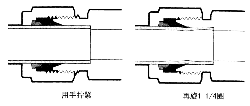
As shown in the figure, put the nut on the tapered end of the connector and then screw it onto the fitting. After tightening it by hand, further tighten it by 1/4 turn with a wrench. (For pipes with diameters of 1/16, 1/8, 3/16 inches; 2, 3, 4 mm, just tighten it by 1/8 turn.)