2.3 Standards for instrument joints
There are mainly two standards for the pipe diameters of instrument pipes: the imperial system and the metric system.
There are mainly two standards for the threads used to connect instruments: NPT and ISO.
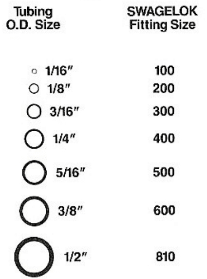
The imperial outer diameters of instrument pipes include the following models: 1/16, 1/8, 3/16, 1/4, 5/16, 3/8, 1/2, 5/8, 3/4, 7/8, 1, 1 ¼, 1 ½, and 2 inches.
The metric outer diameters of instrument pipes include the following models: 2, 3, 4, 6, 8, 10, 12, 14, 15, 16, 18, 20, 22, 25, 28, 30, 32, and 38 mm.
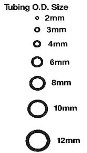
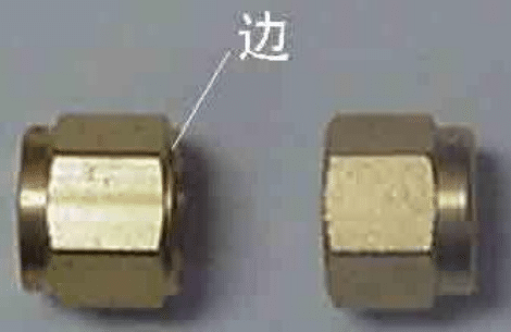
The pipe diameters and joints between the imperial and metric systems cannot be used interchangeably. However, the differences between them are quite small, making it difficult to distinguish (for example, 1/4 inch is equal to 6.35 mm, which is easily confused with 6 mm OD). The only way to distinguish them is to measure with a caliper. In addition, some can be identified by the shape of the pipe joints: there is a ring – shaped edge on the nuts of some metric pipe joints (as shown in the figure), while imperial ones don’t have it.
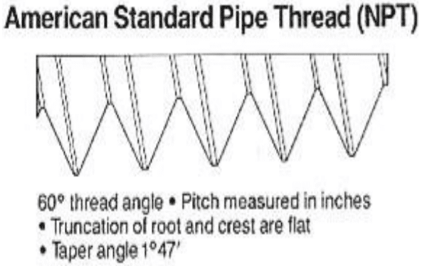
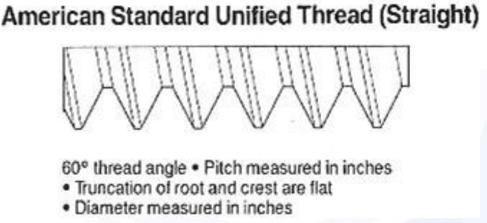
The threads for instrument connections mainly include NPT: American standard pipe thread. It is divided into two types: tapered thread (NPT) and straight thread (ST).
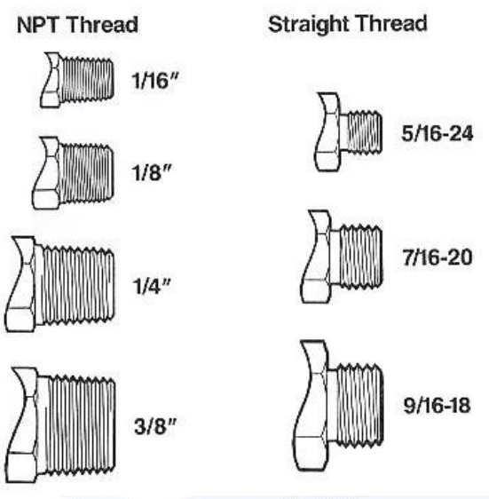
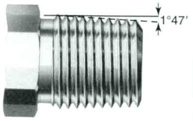
Tapered Thread (NPT Thread): The thread angle is 60°. The pitch is calculated by the number of threads per inch. The root and crest of the thread are flat. The slope angle of the thread is 1°47′. For example, for 1/4″, generally, the inner diameter of the pipe is 1/4″.
Straight Thread: The thread angle is 60°. The pitch is calculated by the number of threads per inch. The root and crest of the thread are flat, and the slope angle of the thread is 0. For example, 5/16 – 24 means the outer diameter of the pipe is 5/16 inches and there are 24 threads per inch.
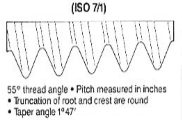
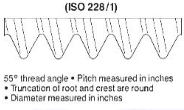
The threads for instrument connections mainly include ISO: International Organization for Standardization, international standard pipe threads. It is divided into two types: ISO 7/1 (RT) and ISO 228/1 (RS).
ISO 7/1 (RT): The thread angle is 55°. The pitch is calculated by the number of threads per inch. The root and crest of the thread are rounded. The slope angle of the thread is 1°47′. For example, if the pipe joint model is 1/4″, it refers to an RT-type pipe joint with an inner pipe diameter of 1/4″.
ISO 228/1 (RS): The thread angle is 55°. The pitch is calculated by the number of threads per inch. The root and crest of the thread are rounded, and the slope angle of the thread is 0. For example, if the pipe joint model is 1/4″, it means an RS-type pipe joint with an inner pipe diameter of 1/4″.
Precautions: Both NPT and ISO 7/1 (RT) are tapered pipe threads with a slope of 1°47′. However, due to the different angles of the thread profiles, they cannot be used interchangeably. Both Straight (ST) and ISO 228/1 (RS) are straight threads, but they also cannot be used interchangeably because of the different thread profiles.
Identification methods:
For male and female NPT threaded joints, there are generally no markings on their outer surfaces. Sometimes, the words “NPT” are marked.
For male and female Straight threaded joints, the word “ST” is marked on their outer surfaces.
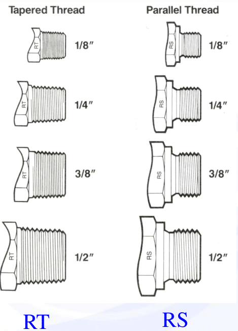
For male and female ISO 7/1 threaded joints, the word “RT” is marked on their outer surfaces.
For female and male ISO 228/1 threaded joints, the words “RS” or “RP” are marked on their outer surfaces.
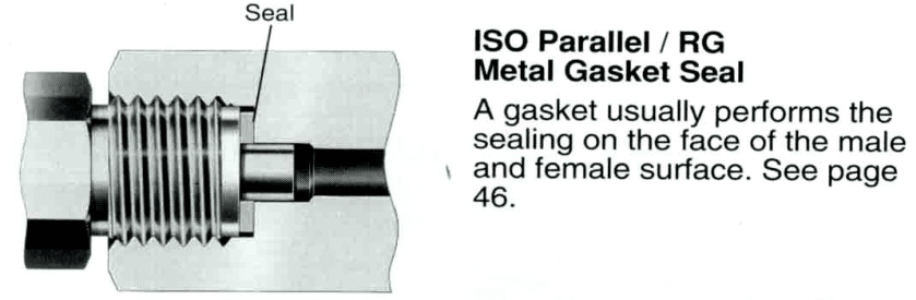
Both Straight and ISO 228/1 are straight threads. Their sealing does not work like that of tapered threads, which can achieve sealing just by tightening directly. Instead, a sealing device must be installed to achieve the sealing purpose. Especially for ISO 228/1 type threads, according to different sealing methods, they are further divided into three types: RS, RP, and RG.
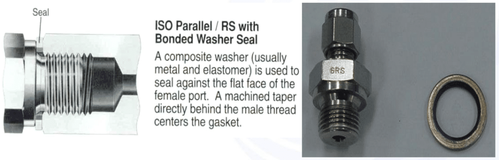
RS: Its fitting port is flat, typically sealed with a steel washer accompanied by a rubber ring, and the extension on the left side of the thread (as shown in the diagram) is tapered.
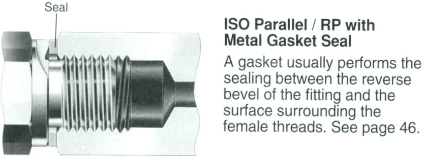
RP: Its joint port is protruding. Usually, a copper washer is used for sealing. The extended part on the left side of the thread (as shown in the figure) is flat.
The RP joint and washer are shown in the figure below. This washer can also be used on RS-type joints.
Note: There are also RS and RP joints that do not use washers.
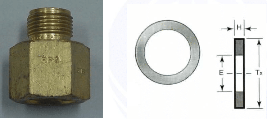
RG: Its washer is usually placed at the front end of the thread (the right – hand end in the illustration) and a copper washer is used for sealing. Generally, RG type is used for pressure gauge joints.
3. Case Studies of Accidents Caused by Fittings
Event 1
At 08:20 on March 20, 2024, in a certain terminal, due to the insufficient coupling between the instrument pipe and the instrument joint, the instrument pipe at the CO₂ pressure – taking port in the decarbonization area was blown off under a high pressure of about 6 MPa, resulting in natural gas leakage.
Cause analysis: The 6 – mm instrument piping provided by the manufacturer was not well – coupled with the on – site 1/4″ OD joint. After tightening with normal force, the OD cap could still be turned by hand. As a result, the instrument pipe was blown off under a high pressure of about 6 MPa.
Event 2
At 16:45 on May 6, 2023, during the daily inspection of the 90 – L (pressure 4.2 Mpa) gas cylinders in the FM200 storage room on a certain platform, the locking nut of a gas cylinder pressure gauge suddenly broke and flew out.
Cause analysis: Usually, the pressure gauge is not connected to the inside of the gas cylinder. When checking the gas cylinder pressure, maintenance personnel need to loosen the locking nut to connect the gas cylinder with the pressure gauge. The copper content of the pressure gauge locking nut was lower than the standard value range, while the lead content was higher than the standard value range, which led to the decrease of the tensile strength and yield strength.